How to Test Continuity in a Long Wire
Contents
- What is Continuity?
- Using a Multimeter
- Steps for Checking Continuity in a Long Wire
- Step 1 – Switch Off Electricity Supply and Disconnect the Wire
- Step 2 – Set Up the Multimeter
- Step 3 – Connect the Multimeter Probes to the Wire
- Step 4 – Remove and Disassemble the Multimeter
- Notes and Other Reminders
Trying to repair faulty electronics but can't figure out what's wrong?
The problem might just be lying in plain sight. People tend to overlook the condition of long wires when repairing electronics. Electrical wires are built to last for years, but other factors like rough handling and exposure to the elements can cause them to break. Checking the wires for continuity is the only way to guarantee your wire is still functional.
Speed up your repairs by learning how to test a long wire for continuity.
What is Continuity?
Continuity exists when two objects are electronically connected.
Wires conduct electricity, so you've established continuity by connecting a simple switch with a light bulb. Likewise, a material that does not conduct electricity, like wood, does not establish continuity. That's because the material does not electronically connect two objects.
On a deeper level, continuity exists when the conductive path of electricity flow is unbroken.
Electrical wires are both conductors and resistors. It controls the flow of electrons and ions to and from each end. Continuity indicates how well electricity travels through a wire. A good continuity reading means that all the wires' conductors are functional.
A continuity test checks for continuity in electronics and electrical components. This is done by using a tester circuit to measure the resistance value.
Lack of continuity causes many issues with electronics and components, such as:
- A blown fuse
- Disfunctional switches
- Blocked circuit paths
- Shorted conductors
- Faulty wiring
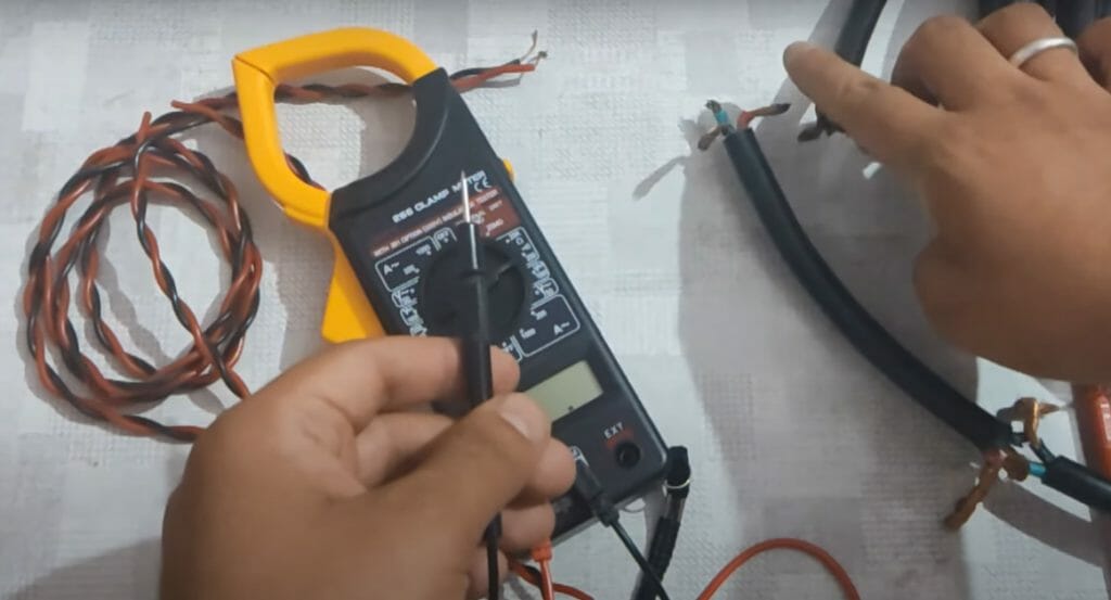
Using a Multimeter
A multimeter is an essential tester circuit for any electronics-related projects.
This handheld tool measures electrical values like the voltage, capacity, and resistance. It comes in analog and digital versions, but the main use and parts remain the same. It comes with two lead probes, a positive red wire, and a black negative wire, that measure electrical values when in contact with electronics.
The cheaper analog multimeter works well as a continuity tester, but you also can invest in digital multimeters for their additional functions and more accurate readings. Digital multimeters sometimes come with a dedicated continuity test function.
Steps for Checking Continuity in a Long Wire
Now that you understand the basics of continuity, it's time to learn how to test a long wire for continuity.
The only tool you'll need to check for continuity is a simple multimeter. But remember to stay safe by wearing basic protective safety equipment when doing this test.
Step 1 – Switch Off Electricity Supply and Disconnect the Wire
Never do a continuity test on a live wire.
Turn off the main circuit that's supplying electricity to the wire. Ensure that there isn't any electricity traveling through the wire, as a live wire can cause unwanted accidents.
Disconnect the wire from any connected components and the circuit itself.
Safely discharge any capacitors present on the circuit before touching the other components. If the wire is connected to components like switches or bulb sockets, then carefully disconnect the wire from them.
Afterward, remove the wire from the circuit. Do this by gently prying off the wire from its connection point. Take care not to do any damage to the wire during this process. Take the fully removed wire to a clear work area.
Step 2 – Set Up the Multimeter
First, turn the dial of the multimeter to Ohm.
The values "1" or "OL" should appear on the display. "OL" means "Open Loop"; it is the highest possible value on the measurement scale. These values mean that there is zero continuity measured.
Connect the probes to the proper jacks on the multimeter.
Connect the black probe to the COM jack (which means common). Connect the red probe to the VΩ jack. Depending on the model of your multimeter, it may have contact points instead of the COM socket. Always refer to the manual if you're unsure about the probe connections.
Don't let the multimeter probe leads touch anything before the continuity test. This can alter the reading obtained. Also, take note of the order in which you connected the wires. This information is needed later when the multimeter is packed away after usage.
Set the range set of the multimeter to the proper value.
The range set value determines the resistance of the component. Lower ranges are used for components that have low resistances. Higher ranges are used to test higher resistances. Setting the multimeter to 200 Ohms is enough to check continuity for long wires.
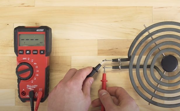
Step 3 – Connect the Multimeter Probes to the Wire
Continuity is non-directional—no need to worry about connecting the probes to the wrong end. Switching the probes' locations does not affect the resistance measurement.
The important thing is to connect the probe leads to the metal of the wire. Place one probe at each end of the wire. Ensure the probe is properly in contact with the wire to get an accurate reading.
The measurement obtained from this continuity tester should show up on the multimeter. There are two measurements to look for, "1" and other values close to 0.
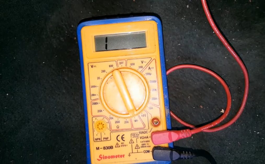
Values close to zero are interpreted as continuity within the probes and wire. This means that the circuit is closed or completed. Electricity can freely flow within the wire without any issues.
The "1" value is interpreted as zero continuity. This value indicates that the circuit of the wire is open. This could mean three possible things:
- There is zero continuity
- There is infinite resistance
- High voltage is present
You can dive deeper into the issue's root, but zero continuity primarily means that the wire is not working properly and must be replaced.
Step 4 – Remove and Disassemble the Multimeter
Pack away the multimeter after checking for continuity.
The proper way of removing the probes from the multimeter is in the reverse order that it was assembled. If the red probe was placed last, remove it first and vice versa. It might seem tedious, but properly disassembling the multimeter extends its lifespan.
Turn off the multimeter and place it in the proper storage area. (1)
Notes and Other Reminders
Always ensure no more electricity is flowing through the wires before checking continuity.
Accidental contact with high voltage often results in electrical shocks and burns. In some cases, it can cause severe injuries or death. Prevent this from happening by ensuring that there is no current flowing through the circuit and its components.
Wearing protective equipment is an excellent precaution against electric currents. Although protective equipment is generally not used for simple continuity checks, it is highly recommended. Newer multimers come equipped with overload protection up to a certain voltage rating. This gives the user some degree of protection against electrical currents. (2)
Always check the manual of your multimeter to learn how to measure resistance.
There are many kinds of multimeter models available in the market, most of which come with different features. Some multimeters come with a continuity button that needs to be pressed while checking continuity. Newer models even give off a beep if continuity is detected. This makes it easier to check continuity without the need to check the value.
Take a look at some of our related articles below.
- How to run overhead electrical wire to garage
- What gauge wire for light fixture
- Can insulation touch electrical wires
References
(1) storage area – https://www.bhg.com/decorating/small-spaces/strategies/creative-storage-ideas-for-small-spaces/
(2) electric current – https://www.britannica.com/science/electric-current
Video References
AMRE Supply
TUSHARA SHARMA
Ratchets And Wrenches
Home & Garden for Mere Mortals
Fast Rust
jonathanthads1976.blogspot.com
Source: https://toolsweek.com/how-to-test-a-long-wire-for-continuity/
0 Response to "How to Test Continuity in a Long Wire"
Post a Comment